

RO Membrane Element for Electronic Grade Ultra Pure Water Polishing
Introduction:Electronic manufacturing, semiconductor cleaning and precision component production require ultra pure water with extremely low dissolved ions, particles and organic residue. Conventional industrial RO permeate still carries residual salts and trace contaminants, so a polishing stage is needed before the water reaches the process point. This RO membrane element is engineered for electronic grade ultra pure water polishing, providing high rejection and stable permeate quality in the final RO or two-stage RO array. It drops into standard pressure vessels, supporting fabs and electronics workshops in maintaining consistent UPW quality and protecting sensitive cleaning processes from ion and particle contamination.
We're here to help:
Easy ways to get the answers you need.
Product parameter:
Product Introduction
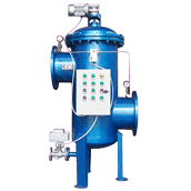
This RO membrane element is developed for the polishing stage of electronic grade ultra pure water systems, where the final RO or second-stage array polishes already treated water to a low conductivity level suitable for semiconductor, electronics and precision cleaning processes. It fits the standard 4040 and 8040 vessel formats, matching central tube, end cap and seal dimensions so it seats directly into the existing water filter housing without adapters or vessel modification. The element works as the final separation stage of a treatment train whose front end typically includes a coarse self-cleaning filter, media pre-treatment, primary RO array and security cartridges that remove silt, colloids and residual particles before feed water reaches the polishing membrane. The membrane grade is selected for high rejection and low extractable matter, keeping residual ions, trace organics and particles within the tight UPW specification. Seals and wetted materials are chosen to minimize leaching into the polished water, and each element is tested for flow, rejection and pressure drop before packing. Dimensions are standard-compatible, so replacement elements can be sourced from multiple qualified channels. This product is an independent compatible replacement; brand names appear only to describe compatibility.
Working Principle

The element is a spiral wound module built from membrane leaves, feed spacer and permeate spacer wound around a central collection tube. Feed water — already pre-treated and partly demineralized by the primary RO — enters the polishing vessel and flows along the feed channel between leaves. Water molecules pass through the polyamide membrane and collect in the permeate channel, then drain into the central tube and exit as polished water. Residual dissolved salts, trace ions and rejected colloids stay in the concentrate stream and leave through the concentrate outlet, which in a two-stage array feeds back or discharges according to the system design.
In a polishing RO, the feed water is already relatively clean, so the membrane's role shifts from bulk impurity removal to fine residual rejection. The high rejection membrane holds back the remaining dissolved ions that the primary stage did not remove, bringing permeate conductivity down to the level required for electronic process water. Because the feed is low in solids, the polishing element faces less heavy fouling than a primary stage, but it must still avoid releasing particles or extractables into the polished stream, which would defeat the purpose of the polishing loop.
The feed spacer and permeate channel are sealed to prevent feed-to-permeate bypass, since even a small leak can raise ion levels in the polished water. The central tube and end seals are matched to the vessel so bypass is minimized across the element array.
UPW systems often run continuously, and performance is tracked by permeate conductivity, flow and differential pressure against the commissioning baseline. As the element ages, rejection drifts and conductivity rises; CIP restores part of the performance, and the element is replaced when polished water quality can no longer meet the electronic specification.
Typical Specifications
| Item | Typical Range |
|---|---|
| Element format | 4040 / 8040 spiral wound, standard dimensions |
| Application | Electronic grade UPW polishing RO arrays |
| Rated permeate flow | 4040: 0.8–1.2 m³/h; 8040: 8–12 m³/h |
| Salt rejection | 99.5 to 99.8 percent, high rejection grade |
| Maximum feed temperature | 45 degrees Celsius |
| Feed pH for operation | 4 to 10 |
| Cleaning pH range | 2 to 11 |
| Rejection characteristic | High residual ion rejection for polishing duty |
| Free chlorine limit | Below 0.1 ppm, protect by pre-treatment |
| Material requirement | Low extractable seals and wetted parts |
| End connection | Standard central tube and seal |
Core Advantages
High residual ion rejection:
high rejection grade polishes primary RO permeate to the low conductivity required for electronic process water.
Low extractable construction:
seals and wetted materials minimize leaching, keeping polished water free of added particles or organics.
Standard drop-in fit:
central tube, end cap and seal match mainstream formats, replacement without housing modification.
Stable polishing performance:
consistent rejection holds UPW conductivity within the tight specification as feed quality varies.
Multi-supplier compatible:
standard dimensions allow spare elements from qualified channels, reducing stock dependency.
Tested per batch:
flow, rejection and pressure drop verified before packing, matching the UPW system baseline.
Application Scenarios

Semiconductor and wafer cleaning UPW polishing RO
Electronic component and PCB manufacturing pure water
Precision instrument and optical part cleaning water
Two-stage RO polishing arrays in electronics plants
Replacing aged polishing elements in UPW loops
Laboratory and R&D ultra pure water systems
Pharmaceutical and high-purity process water polishing
Battery and new energy component manufacturing water
Competitive Position and Replacement Notes
Electronics UPW operators usually meet three issues. Original polishing elements carry a high unit price, and a fab with multiple vessels builds a large spare budget over the year. Second, some generic elements copy the dimensions but use standard-grade membrane and seals that leach particles or organics, so polished water fails the tight UPW specification even when conductivity looks acceptable. Third, replacement elements are often tied to one brand channel, and a polishing loop waiting on spares risks interrupting a sensitive production line.
Our polishing element is selected against the UPW target rather than a generic industrial grade. Rejection level, seal material and extractable control are matched to the electronic water specification, and the standard vessel format means no adapters are needed. Each batch is tested before packing, and seals and end parts are available as consumables. We review the primary RO and pre-treatment condition alongside the element, because polishing performance depends on clean feed entering the second stage; a polishing membrane cannot compensate for upstream silt, chlorine or organic breakthrough.
This element is supplied as an independent compatible replacement and is not affiliated with any membrane equipment or electronics brand. Brand references appear only to describe compatibility.
Selection Guide
Confirm element format and vessel:
4040 or 8040, central tube size, seal type and elements per vessel.
Define the UPW target:
conductivity, resistivity, particle and organic limits for the specific electronic process.
Provide the polishing stage feed analysis:
residual TDS, silica, hardness, chlorine and organic level after the primary RO.
Select rejection grade:
high rejection for final polishing; confirm whether the array is single or two stage.
Verify material requirements:
seal and wetted part extractable limits for the electronics or pharmaceutical standard.
Check pump pressure and array recovery, so the element grade matches the polishing loop design.
Plan spare stock by vessel position and replacement cycle, since polishing elements are often changed on a fixed UPW maintenance schedule.
Installation and Maintenance Notes
Flush the new element with polished water before start-up, and follow the break-in schedule, raising operating pressure gradually over the first run period. Lubricate seals with a compatible low-extractable lubricant, seat the element squarely in the vessel, and align the connector to prevent bypass that would raise polished water conductivity.
Record permeate conductivity, flow, rejection and differential pressure on the first day as the baseline. Monitor primary RO performance and pre-treatment condition, because any upstream breakthrough reaches the polishing stage first. Run CIP when normalized flow or rejection drops beyond the set limit, using cleaners approved for the polishing loop. Never run the element with free chlorine above the limit, since oxidation damage is irreversible.
During long shutdowns, preserve elements in biocide solution approved for UPW service. Replace elements when polished water quality cannot be restored by cleaning, and record installation date and vessel position so the worst-performing polishing vessel can be traced.
FAQ
Q1: What is the difference between a primary RO membrane and a polishing RO membrane?
A1: The primary stage removes bulk salts, hardness and solids from raw water. The polishing stage polishes already treated water, holding back residual ions to reach the tight UPW conductivity and particle specification. Grades and seal materials are selected for these different duties.
Q2: Can this element be used as the only RO stage in an electronics plant?
A2: It is designed for polishing duty. Most UPW systems use a primary RO array followed by this polishing stage, then further polishing such as EDI or mixed bed. A single-stage design should be reviewed against the raw water analysis.
Q3: How is polished water quality verified after element replacement?
A3: Conductivity or resistivity is measured at the polishing outlet, and particle and organic tests are run according to the plant's UPW protocol. Compare results against the commissioning baseline before returning the loop to production.
Q4: Does the polishing element need special pre-treatment?
A4: It relies on the primary RO and upstream pre-treatment to deliver clean feed. Security cartridges, chlorine removal and media filtration must be maintained, because polishing membranes are sensitive to silt, chlorine and organic breakthrough.
Q5: How long does the element last in a UPW polishing loop?
A5: With clean feed and regular CIP, typical service life is 2 to 3 years. UPW plants often replace polishing elements on a fixed cycle to protect product quality; conductivity, flow and differential pressure trends confirm the actual timing.
Related Products
BW30FR-400/34 Water Treatment RO Reverse Osmosis Membrane
40-inch RO membrane water purifier membrane
High Efficiency Reverse Osmosis Membrane for Water Treatment
Commercial Reverse Osmosis Membrane for Pure Water System
High Salt Rejection RO Membrane for Brackish Water Treatment
Please fill in your procurement needs and contact information